Web Analytics
Part Datasheet Search > FET Drivers > IR2153 Application Note
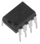
Images are for reference

IR2153 Application Note

Part Series:
IR2153 Series
Category:
FET Drivers
Description:
MOSFET DRVR 600V 0.4A 2Out Hi/Lo Side Half Brdg Inv/Non-Inv 8Pin SOIC
Updated Time: 2023/01/13 01:20:41 (UTC + 8)

IR2153 Application Note FET Drivers

30 Pages
Infineon
MOSFET DRVR 600V 0.4A 2Out Hi/Lo Side Half Brdg Inv/Non-Inv 8Pin PDIP T/R
30 Pages
Infineon
MOSFET DRVR 600V 2Out Hi/Lo Side Half Brdg Inv/Non-Inv 8Pin SOIC
30 Pages
Infineon
Self-Oscillating 600V Half Bridge Driver IC with typical 0.18A source and 0.26A sink currents in 8 Lead PDIP package for IGBTs and MOSFETs.
30 Pages
Infineon
MOSFET DRVR 600V 2Out Hi/Lo Side Half Brdg Inv/Non-Inv 8Pin PDIP
30 Pages
Infineon
Self-Oscillating 600V Half Bridge Driver IC with typical 0.18A source and 0.26A sink currents in 8 Lead PDIP package for IGBTs and MOSFETs.
30 Pages
Infineon
Self-Oscillating 600V Half Bridge Driver IC with typical 0.18A source and 0.26A sink currents in 8 Lead SOIC package for IGBTs and MOSFETs. Also available in 8 Lead PDIP.
30 Pages
Infineon
Self-Oscillating 600V Half Bridge Driver IC with typical 0.18A source and 0.26A sink currents in 8 Lead PDIP package for IGBTs and MOSFETs. Also available in 8 Lead SOIC.

IR2153PBF - Infineon Specifications

TYPE
DESCRIPTION
Mounting Style
Through Hole
Number of Pins
8 Pin
Supply Voltage (DC)
10.0V (min)
Operating Voltage
10V ~ 16.8V
Case/Package
PDIP-8
show more

IR2153PBF - Infineon Function Overview

The IR2153PBF is a self-oscillating Half-bridge Gate Driver IC incorporates a high voltage half-bridge gate driver with a front end oscillator similar to the industry standard CMOS 555 timer. The IC provides more functionality and is easier to use. A shutdown feature has been designed into the CT pin, so that both gate driver outputs can be disabled using a low voltage control signal. In addition the gate driver output pulse widths are the same once the rising under-voltage lockout threshold on VCC has been reached, resulting in a more stable profile of frequency vs. time at start-up. Noise immunity has been improved significantly, both by lowering the peak DI/DT of the gate driver and by increasing the under-voltage lockout hysteresis to 1V.
True micro power start-up
Tighter initial dead-time control
Low temperature coefficient dead time
Shutdown features on CT pin
Lower power level-shifting circuit
Constant LO, HO pulse widths at start-up
Low side output in phase with RT
Excellent latch immunity on all inputs and outputs
Finally special attention has been paid to maximizing the latch immunity of the device and providing comprehensive ESD protection all pins.
show more
Part Datasheet PDF Search
Loading...
72,405,303 Parts Datasheet PDF, Update more than 5,000 PDF files ervery day.
Relate Parts