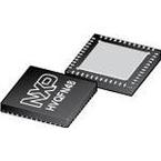
●The MC9S08QE128CFT is a 8-bit Microcontroller based on enhanced HCS08 CPU (25MHz bus) with CISC architecture operates at a maximum frequency of 50MHz. The device incorporates 128kB internal flash, 8kB internal RAM, 10-channel 12-bit A/D converter and 38 general-purpose I/O pins. This device also features peripherals like one inter-integrated circuit (IIC) bus module to operate at up to 100kbps, two serial peripheral interface modules (SPI), two serial communications interface (SCI) and an analog comparator. Internal clock source (ICS) containing a frequency-locked-loop (FLL) controlled by internal or external reference, precision trimming of internal reference allowing 0.2% resolution and 2% deviation. Watchdog computer operating properly (COP) reset with option to run from dedicated 1kHz internal clock source.
● HC08 Instruction set with added BGND instruction
● Support for up to 32 Interrupt/reset sources
● Security circuitry to prevent unauthorized access to RAM and flash contents
● Two low power stop modes; reduced power wait mode
● Peripheral clock enable register can disable clocks to unused modules
● Very low power external oscillator can be used in stop3 mode
● Very low power real time interrupt for use in run, wait and stop modes
● 6µs Typical wake up time from stop modes
● Loop-control pierce oscillator
● Internal clock source (ICS)
● Low-voltage detection with reset or interrupt; selectable trip points
● Illegal opcode detection with reset
● Flash block protection
● Single-wire background debug interface
● Breakpoint capability to allow single breakpoint setting during in-circuit debugging
● On-chip in-circuit emulator (ICE) debug module
● RTC - 8-bit modulus counter with binary or decimal based prescaler
● 16 KBI Interrupts with selectable polarity
● Hysteresis and configurable pull-up device on all input pins
● SET/CLR registers on 16 pins (PTC and PTE)


