Web Analytics
Part Datasheet Search > PWM Controllers > TL3842 Datasheet PDF
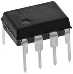
Images are for reference

TL3842 Datasheet PDF

Part Series:
TL3842 Series
Category:
PWM Controllers
Description:
Current Mode PWM Controller 0V to 30V 200mA 500kHz 8Pin PDIP Tube
Updated Time: 2023/01/13 02:12:21 (UTC + 8)

TL3842 Datasheet PDF PWM Controllers

27 Pages
TI
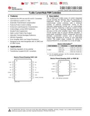
Current Mode PWM Controller 0V to 30V 200mA 500kHz 14Pin SOIC T/R
27 Pages
TI
Current Mode PWM Controller 0V to 30V 200mA 500kHz 8Pin SOIC T/R
27 Pages
TI
Current Mode PWM Controller 0V to 30V 200mA 500kHz 8Pin SOIC Tube
27 Pages
TI
Current Mode PWM Controller 0V to 30V 200mA 500kHz 8Pin SOIC T/R
27 Pages
TI
Current Mode PWM Controller 0V to 30V 200mA 500kHz 8Pin SOIC Tube
27 Pages
TI
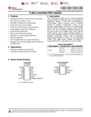
IC REG CTRLR BST FLYBK PWM 8-DIP
27 Pages
TI
Current Mode PWM Controller 0V to 30V 200mA 500kHz 8Pin PDIP Tube
27 Pages
TI
Current Mode PWM Controller 0V to 30V 200mA 500kHz 8Pin SOIC T/R
27 Pages
TI
Current Mode PWM Controller 0V to 30V 200mA 500kHz 8Pin SOIC Tube
27 Pages
TI
IC REG CTRLR BST FLYBK PWM 8SOIC
25 Pages
TI
Current Mode PWM Controller 0V to 30V 200mA 500kHz 8Pin PDIP Tube
25 Pages
TI
Current Mode PWM Controller 0V to 30V 200mA 500kHz 8Pin SOIC Tube
25 Pages
TI
Current Mode PWM Controller 0V to 30V 200mA 500kHz 14Pin SOIC T/R
24 Pages
TI
Current Mode PWM Controller 0V to 30V 200mA 500kHz 14Pin SOIC Tube
24 Pages
TI
Current Mode PWM Controller 0V to 30V 200mA 500kHz 8Pin PDIP Tube

TL3842P - TI Specifications

TYPE
DESCRIPTION
Mounting Style
Through Hole
Frequency
500 kHz
Number of Pins
8 Pin
Supply Voltage (DC)
30.0V (max)
Operating Voltage
16V ~ 30V
show more

TL3842P - TI Function Overview

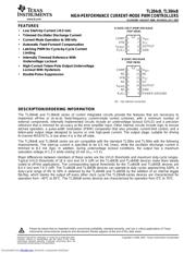
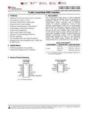
The TL3842P is a current-mode PWM Controller provides the features that are necessary to implement off-line or DC-to-DC fixed-frequency current-mode control schemes with a minimum number of external components. Some of the internally implemented circuits are an under-voltage lockout (UVLO), featuring a start-up current of less than 1mA and a precision reference trimmed for accuracy at the error amplifier input. Other internal circuits include logic to ensure latched operation, a pulse-width modulation (PWM) comparator (that also provides current-limit control) and a totem-pole output stage designed to source or sink high-peak current. The output stage, suitable for driving N-channel MOSFETs, is low when it is in the OFF state.
Optimized for Off-line and DC-to-DC converters
<1mA Low start-up current
Automatic feed-forward compensation
Pulse-by-pulse current limiting
Enhanced load-response characteristics
Under-voltage lockout with hysteresis
Double-pulse suppression
High-current totem-pole output
Internally trimmed band gap reference
This device has limited built-in ESD protection, leads should be shorted together or the device placed in conductive foam during storage or handling to prevent electrostatic damage to the MOS gates.
show more
Part Datasheet PDF Search
Loading...
72,405,303 Parts Datasheet PDF, Update more than 5,000 PDF files ervery day.
Relate Parts