Web Analytics
Part Datasheet Search > Logic ICs > 74LVC1G74 Datasheet PDF
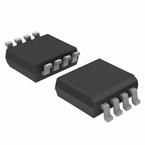
Images are for reference

74LVC1G74 Datasheet PDF

Part Series:
74LVC1G74 Series
Category:
Logic ICs
Description:
IC D-TYPE POS TRG SNGL 8VSSOP
Updated Time: 2023/01/13 02:13:43 (UTC + 8)

74LVC1G74 Datasheet PDF Logic ICs

27 Pages
NXP
Flip Flop D-Type Pos-Edge 1Element 8Pin XSON T/R
27 Pages
NXP
Flip Flop D-Type Pos-Edge 1Element 8Pin XQFN8U
26 Pages
Nexperia
IC D-TYPE POS TRG SNGL 8VSSOP
26 Pages
NXP
Flip Flop D-Type Pos-Edge 1Element 8Pin VSSOP
26 Pages
NXP
Flip Flop D-Type Pos-Edge 1Element 8Pin XSON T/R
26 Pages
Nexperia
IC D-TYPE POS TRG SNGL 8XSON
26 Pages
Nexperia
IC D-TYPE POS TRG SNGL 8XQFN
26 Pages
NXP
IC LVC/LCX/Z SERIES, POSITIVE EDGE TRIGGERED D FLIP-FLOP, COMPLEMENTARY OUTPUT, PDSO8, 3MM WIDTH, 0.5MM LENGTH, PLASTIC, SOT505-2, TSSOP-8, FF/Latch
26 Pages
Nexperia
IC D-TYPE POS TRG SNGL 8XSON
26 Pages
Nexperia
IC D-TYPE POS TRG SNGL 8XSON
26 Pages
NXP
Flip Flop D-Type Pos-Edge 1Element 8Pin XSON8U
26 Pages
NXP
Single D-type flip-flop with set and reset; positive edge trigger
26 Pages
NXP
Single D-type flip-flop with set and reset; positive edge trigger
20 Pages
Nexperia
IC D-TYPE POS TRG SNGL 8TSSOP
18 Pages
NXP
Flip Flop D-Type Pos-Edge 1Element 8Pin VSSOP T/R
18 Pages
NXP
Flip Flop D-Type Pos-Edge 1Element Automotive 8Pin XSON T/R

74LVC1G74DC,125 - Nexperia Specifications

TYPE
DESCRIPTION
Mounting Style
Surface Mount
Frequency
280 MHz
Number of Pins
8 Pin
Capacitance
4 pF
Case/Package
VSSOP-8
show more

74LVC1G74DC,125 - Nexperia Function Overview

The 74LVC1G74DC is a single positive-edge triggered D-type Flip-flop with individual data (D) inputs, clock inputs, set (SD\\) and reset (RD\\) inputs and complementary Q and Q outputs. This device is fully specified for partial power-down applications using IOFF. The IOFF circuitry disables the output, preventing damaging backflow current through the device when it is powered down. The set and reset are asynchronous active low inputs and operate independently of the clock input. Information on the data input is transferred to the Q output on the low-to-high transition of the clock pulse. The D inputs must be stable one set-up time prior to the low-to-high clock transition for predictable operation. Schmitt trigger action at all inputs makes the circuit highly tolerant of slower input rise and fall times.
High noise immunity
CMOS low power consumption
Latch-up performance exceeds 250mA
Direct interface with TTL levels
±24mA Output drive current
show more
Part Datasheet PDF Search
Loading...
72,405,303 Parts Datasheet PDF, Update more than 5,000 PDF files ervery day.
Relate Parts