Part Datasheet Search > - > UC2825 Datasheet PDF
Images are for reference
UC2825 Datasheet PDF
Part Series:
UC2825 Series
Category:
-
Description:
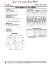
The UC1825 family of PWM control ICs is optimized for high frequency switched mode power supply applications
Document:
Updated Time: 2023/01/13 02:25:34 (UTC + 8)
UC2825 - Datasheet PDF

UC2825 Datasheet PDF -
21 Pages
TI
TEXAS INSTRUMENTS UC2825AQDWREP Current/Voltage Mode PWM Controller, 0 outputs, 12V-20V supply, 2V/200mA out, 1.15kHz, SOIC-16
21 Pages
TI
TEXAS INSTRUMENTS UC2825AMDWREP Current/Voltage Mode PWM Controller, 2Outputs, 12V-20V supply, 2V/200mA out, 1.15kHz, SOIC-16
20 Pages
TI
Current Mode PWM Controller, 2Outputs, 12V-20V supply, 2V/500mA out, 1MHz, DIP-16
19 Pages
TI
TEXAS INSTRUMENTS UC2825BDW Current Mode PWM Controller, 2Outputs, 12V-20V supply, 2V/200mA out, 1MHz, SOIC-16
19 Pages
TI
The UC1825 family of PWM control ICs is optimized for high frequency switched mode power supply applications
17 Pages
TI
Automotive 8.4V to 22V, Up to 1MHz PWM Controller 16-SOIC -40℃ to 125℃
Part Datasheet PDF Search
72,405,303 Parts Datasheet PDF, Update more than 5,000 PDF files ervery day.
