Web Analytics
Part Datasheet Search > PWM Controllers > UCC3808 Datasheet PDF
Images are for reference

UCC3808 Datasheet PDF

Part Series:
UCC3808 Series
Category:
PWM Controllers
Description:
Current Mode PWM Controller 1A 1000kHz 8Pin SOIC Tube
Updated Time: 2023/01/13 02:31:29 (UTC + 8)

UCC3808 Datasheet PDF PWM Controllers

24 Pages
TI
Current Mode PWM Controller 1A 50kHz to 1000kHz 8Pin TSSOP Tube
24 Pages
TI
Current Mode PWM Controller 1A 50kHz to 1000kHz 8Pin SOIC T/R
24 Pages
TI
Current Mode PWM Controller 1A 50kHz to 1000kHz 8Pin TSSOP T/R
24 Pages
TI
Current Mode PWM Controller 1A 50kHz to 1000kHz 8Pin SOIC Tube
22 Pages
TI
Current Mode PWM Controller 1A 1000kHz 8Pin SOIC Tube
22 Pages
TI
Current Mode PWM Controller 1A 1000kHz 8Pin SOIC Tube
22 Pages
TI
Current Mode PWM Controller 1A 1000kHz 8Pin PDIP Tube
22 Pages
TI
Current Mode PWM Controller 1A 1000kHz 8Pin PDIP Tube
22 Pages
TI
Current Mode PWM Controller 1A 1000kHz 8Pin SOIC T/R
21 Pages
TI
Current Mode PWM Controller 1A 1000kHz 8Pin SOIC Tube
21 Pages
TI
TEXAS INSTRUMENTS UCC3808AD-2 PWM Controller, 10V supply, 1MHz, 500mV/100mA out, SOIC-8
21 Pages
TI
Current Mode PWM Controller 1A 1000kHz 8Pin SOIC T/R
21 Pages
TI
Current Mode PWM Controller 1A 1000kHz 8Pin PDIP Tube
21 Pages
TI
Current Mode PWM Controller 1A 1000kHz 8Pin SOIC T/R
21 Pages
TI
Current Mode PWM Controller 1A 1000kHz 8Pin TSSOP Tube
21 Pages
TI
Current Mode PWM Controller 1A 1000kHz 8Pin PDIP Tube

UCC3808D-1 - TI Specifications

TYPE
DESCRIPTION
Mounting Style
Surface Mount
Frequency
1 MHz
Number of Pins
8 Pin
Supply Voltage (DC)
10.0V (min)
Case/Package
SOIC-8
show more

UCC3808D-1 - TI Function Overview

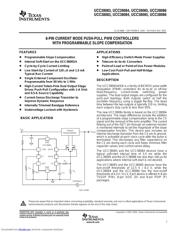
The UCC3808D-1 is a low power current-mode BiCMOS Push-pull Pulse Width Modulation (PWM) Controller contains all of the control and drive circuitry required for offline or DC to DC fixed frequency current-mode switching power supplies with minimal external parts count. The UCCx808-x dual output drive stages are arranged in a push-pull configuration. Both outputs switch at half the oscillator frequency using a toggle flip-flop. The dead time between the two outputs is typically 60 to 200ns depending on the values of the timing capacitor and resistors, thus limiting each output stage duty cycle to less than 50%.
Internal soft-start
On-chip error amplifier with 2MHz Gain bandwidth
On-chip VDD Clamping
Output drive stages capable of 500mA Peak
High-speed
Low-power
Green product and no Sb/Br
Device has limited built-in ESD protection, leads should be shorted together or the device placed in conductive foam during storage or handling to prevent electrostatic damage to the MOS gates.
show more
Part Datasheet PDF Search
Loading...
72,405,303 Parts Datasheet PDF, Update more than 5,000 PDF files ervery day.

Relate Parts